Click to
enlarge
and double
click t
reduce
cgsgsdg
fdbfbhfdnhdfhndfhdf
shape. These small isolated
watersheds provide excellent control of
infiltration and the micro-climate,
thereby greatly accelerating re-
vegetation processes.
R
o
l
l
e
r
Categories

How the Imprinting Machine Works
During
the
past
two
decades,
the
general
specifications
for
land
imprinters
were
derived
from
the
principles
of
soil
mechanics
and
the
hydro-biotic
function
of
soil
imprints.
Mechanically,
imprints
are
formed
through
downward
acting
forces
applied
to
angular
steel
teeth.
Troughs
or
indentations
are
formed
through
soil
compression
and
shearing,
whereas
adjacent
crests
or
ridges
are
formed
by
an
embossing
(lifting)
process.
Thus,
the
original
soil
surface
lies
in
a
plane
about
midway
between
the
imprint
trough
and
crest.
A
5-cm
(two
inch)
gap
around
each
tooth
facilitates
these
two
interacting
processes
with
minimal
soil
disturbance and compaction.
Imprints
are
25-cm
(10
inches)
long,
V-
shaped
troughs
or
micro-watersheds
which
funnel
resources
to
the
bottom
of
the
vee
where
they
can
work
in
concert
to
germinate
seeds
and
establish
seedlings.
Each
micro-watershed
is
about
30-cm
(one-foot)
square
in
surface
area
and
can
hold
several
liters
of
rainwater
on
level
ground.
This
is
enough
water
to
germinate
and
establish
one
or
more
seeds
or
seedlings.
Imprints
are
staggered
and
separated
by
5-cm
(two
inch)
wide
dikes
at
the
soil
surface
for
safe
storage
of
rainwater
until
it
infiltrates.
The
staggering
also
gives
plants
more
room
to
develop
and
better
exposure
to
vital
resources
including
water
and
light.
Imprints
that
satisfy
the
general
specifications
are
pictured
in
figure
1.
Such
imprints
will
almost
always
lead
to
successful
if
the
seed
mix
is
adequate.
Such
imprints
are
stable
enough
to
wait
several
years
for
adequate rain to occur in the desert.


The Roller Blades
Roller Categories
To
assist
readers
who
wish
to
make
their
own
imprinters,
specifications
are
given
in
U.S.
Customary
(English)
units.
The
structural
steel
used
to
fabricate
imprinters
is
available
in
these
units.
Conversion
factors
are
given
for
the
convenience
of
those
working
in
countries
where
steel
has
metric
dimensions.
Six
categories
of
imprinting
rollers
result
from
various
combinations
of
2
angle
sizes
(6"x
6"
&
8"
x
8"),
2
angle
shapes
(straight
and
bowlegged)
and
two
cylindrical
core
diameters
(20"
&
24").
Category
specifications
are
given
in
the
table
below.
Angular
teeth
are
welded
radially
around
the
core
to
form
6
or
8
pointed
star
rings.
Tooth
length
is
10
inches
and
the
spacing
between
rings
is
about
2
inches.
Thus,
there
is
one
star
ring
for
each
12
inches
of
imprinting
roller
length.
Points
on
adjacent
star
rings
are
staggered
to
suppress
gully
formation.
The
radial
basal
spacing
of
imprinting
teeth
is
also
about
2
inches.
This
2
inch
gap
around
the
base
of
each
tooth
improves
penetration
into
the
soil
while
providing
a
dam
between
adjacent
imprints
for
safe
storage
of
collected
rain
or
irrigation
water
until
it
infiltrates.
All
six
categories
of
imprinting
rollers
make
imprints
or
micro-watersheds
about
12
inches
square
in
size
and
shape.
These
small
isolated
watersheds
provide
excellent
control
of
infiltration
and
the
microclimate,
greatly
accelerating
the
revegetation
processes.
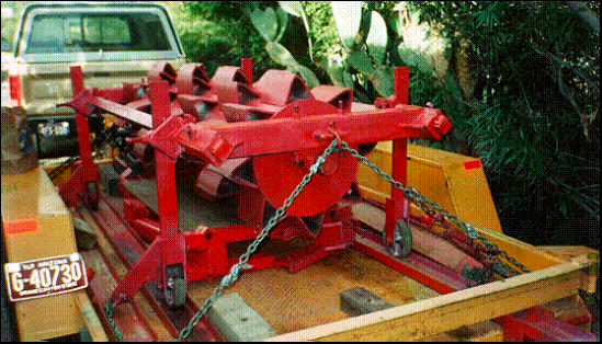
The Tow Frame
T
he
front
and
rear
of
the
tow
frame
are
square
tool
bars
which
permit
the
use
of
commercial
tool
clamps
for
easy
attachment
of
hitches
and
accessories
(Figures
1
&
2).
Typically
the
draw
bar
tongue
is
removed
for
trailer
hauling
to
reduce
the
width
of
the
load.
Since
the
front
and
rear
of
the
tow
frame
are
identical,
hitches
can
be
attached
to
either
side
to
reverse
the
direction
of
roller
rotation.
This
feature
nearly
doubles
the
life
of
imprinting
teeth,
the
tips
of
which
concave
sharpen on their leading edges
Click on pictures to enlarge/read -- double click to reduce
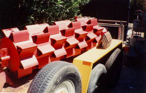
Figure 2
Tow
frame
and
imprint
rollers
with
loading/unloading wheels attached.
•
Frame
Shape
and
Size:
Rectangular
to
fit
rollers 3,4,5,6,7,8,9 & 10 feet in length
•
Rear tool bar: (2 ¼-inch side)
•
Frame
Ends:
Clamped
to
tool
bars
with
center bearing bracket
•
Roller
Axle:Full-length,
cold-rolled
steel,
2
½-inch diameter
•
Axle
Bearings:
Pillow
block
type
with
cast
steel
housing
and
double
tapered
roller
bearings
•
for 2 ½-inch axle
•
Tool Attachments:
•
(1) Draw bar tongue for field operation
•
(2) Trailer loading and unloading wheels
•
(3) Three-point hitch (optional)
•
(4) Ripping Arms (optional)
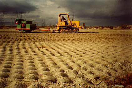
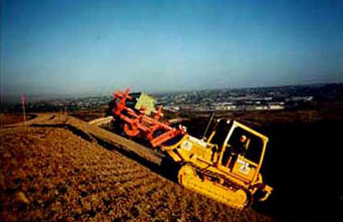
Figure
1:
Imprinter
tow
frame
attached
to
a
dozer
blade
to
form
a
steep-slope
imprinter.
Tractor
hydraulics
force
imprinting
teeth
into
the ground.
Category II, 7-foot imprinting rollers
designed for re-vegetating steep
slopes.
Well-formed
imprints
efficiently
establish
vegetation
on
severely
degraded
land.
Ripping
shanks
at
the
rear
of
the
tractor
loosen hard soil spots enough to imprint.


The Nuts and Bolts of our Imprinting Machines


more info


To email us, click on logo to left


How the Imprinting Machine Works
During
the
past
two
decades,
the
general
specifications
for
land
imprinters
were
derived
from
the
principles
of
soil
mechanics
and
the
hydro-biotic
function
of
soil
imprints.
Mechanically,
imprints
are
formed
through
downward
acting
forces
applied
to
angular
steel
teeth.
Troughs
or
indentations
are
formed
through
soil
compression
and
shearing,
whereas
adjacent
crests
or
ridges
are
formed
by
an
embossing
(lifting)
process.
Thus,
the
original
soil
surface
lies
in
a
plane
about
midway
between
the
imprint
trough
and
crest.
A
5-cm
(two
inch)
gap
around
each
tooth
facilitates
these
two
interacting
processes
with
minimal
soil
disturbance and compaction.
Imprints
are
25-cm
(10
inches)
long,
V-
shaped
troughs
or
micro-watersheds
which
funnel
resources
to
the
bottom
of
the
vee
where
they
can
work
in
concert
to
germinate
seeds
and
establish
seedlings.
Each
micro-watershed
is
about
30-cm
(one-foot)
square
in
surface
area
and
can
hold
several
liters
of
rainwater
on
level
ground.
This
is
enough
water
to
germinate
and
establish
one
or
more
seeds
or
seedlings.
Imprints
are
staggered
and
separated
by
5-cm
(two
inch)
wide
dikes
at
the
soil
surface
for
safe
storage
of
rainwater
until
it
infiltrates.
The
staggering
also
gives
plants
more
room
to
develop
and
better
exposure
to
vital
resources
including
water
and
light.
Imprints
that
satisfy
the
general
specifications
are
pictured
in
figure
1.
Such
imprints
will
almost
always
lead
to
successful
if
the
seed
mix
is
adequate.
Such
imprints
are
stable
enough
to
wait
several
years
for
adequate rain to occur in the desert.
The Roller Blades
Roller Categories
To
assist
readers
who
wish
to
make
their
own
imprinters,
specifications
are
given
in
U.S.
Customary
(English)
units.
The
structural
steel
used
to
fabricate
imprinters
is
available
in
these
units.
Conversion
factors
are
given
for
the
convenience
of
those
working
in
countries
where
steel
has
metric
dimensions.
Six
categories
of
imprinting
rollers
result
from
various
combinations
of
2
angle
sizes
(6"x
6"
&
8"
x
8"),
2
angle
shapes
(straight
and
bowlegged)
and
two
cylindrical
core
diameters
(20"
&
24").
Category
specifications
are
given
in
the
table
below.
Angular
teeth
are
welded
radially
around
the
core
to
form
6
or
8
pointed
star
rings.
Tooth
length
is
10
inches
and
the
spacing
between
rings
is
about
2
inches.
Thus,
there
is
one
star
ring
for
each
12
inches
of
imprinting
roller
length.
Points
on
adjacent
star
rings
are
staggered
to
suppress
gully
formation.
The
radial
basal
spacing
of
imprinting
teeth
is
also
about
2
inches.
This
2
inch
gap
around
the
base
of
each
tooth
improves
penetration
into
the
soil
while
providing
a
dam
between
adjacent
imprints
for
safe
storage
of
collected
rain
or
irrigation
water
until
it
infiltrates.
All
six
categories
of
imprinting
rollers
make
imprints
or
micro-watersheds
about
12
inches
square
in
size
and
shape.
These
small
isolated
watersheds
provide
excellent
control
of
infiltration
and
the
microclimate,
greatly
accelerating
the
revegetation
processes.
The Tow Frame
T
he
front
and
rear
of
the
tow
frame
are
square
tool
bars
which
permit
the
use
of
commercial
tool
clamps
for
easy
attachment
of
hitches
and
accessories
(Figures
1
&
2).
Typically
the
draw
bar
tongue
is
removed
for
trailer
hauling
to
reduce
the
width
of
the
load.
Since
the
front
and
rear
of
the
tow
frame
are
identical,
hitches
can
be
attached
to
either
side
to
reverse
the
direction
of
roller
rotation.
This
feature
nearly
doubles
the
life
of
imprinting
teeth,
the
tips
of which concave sharpen on their leading edges
Click on pictures to enlarge/read -- double click to reduce
Figure 2
Tow
frame
and
imprint
rollers
with
loading/unloading wheels attached.
•
Frame
Shape
and
Size:
Rectangular
to
fit
rollers
3,4,5,6,7,8,9
&
10
feet
in
length
•
Rear tool bar: (2 ¼-inch side)
•
Frame Ends: Clamped to tool bars with center bearing bracket
•
Roller Axle:Full-length, cold-rolled steel, 2 ½-inch diameter
•
Axle
Bearings:
Pillow
block
type
with
cast
steel
housing
and
double
tapered
roller bearings
•
for 2 ½-inch axle
•
Tool Attachments:
•
(1) Draw bar tongue for field operation
•
(2) Trailer loading and unloading wheels
•
(3) Three-point hitch (optional)
•
(4) Ripping Arms (optional)
Figure
1:
Imprinter
tow
frame
attached
to
a
dozer
blade
to
form
a
steep-slope
imprinter.
Tractor
hydraulics force imprinting teeth into the ground.
Category II, 7-foot imprinting
rollers designed for re-
vegetating steep slopes.
Well-formed
imprints
efficiently
establish
vegetation
on
severely
degraded
land.
Ripping
shanks
at
the
rear
of
the
tractor
loosen hard soil spots enough to imprint.

The Nuts and Bolts of our Imprinting Machines


more info


Email Web Mistress

To email us, click on
logo to left